KiCad to FreeCAD
If you have read some of the previous articles, there is a good chance that you’ve seen snippets of my experience in KiCad. KiCad is a tool that specialises in the design of electronic schemas and circuit boards. If you’re working on a small electronics project, there is a high likely-hood that it could be helpful for you. The end result of a KiCad project looks like this:
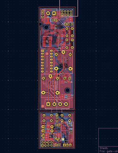
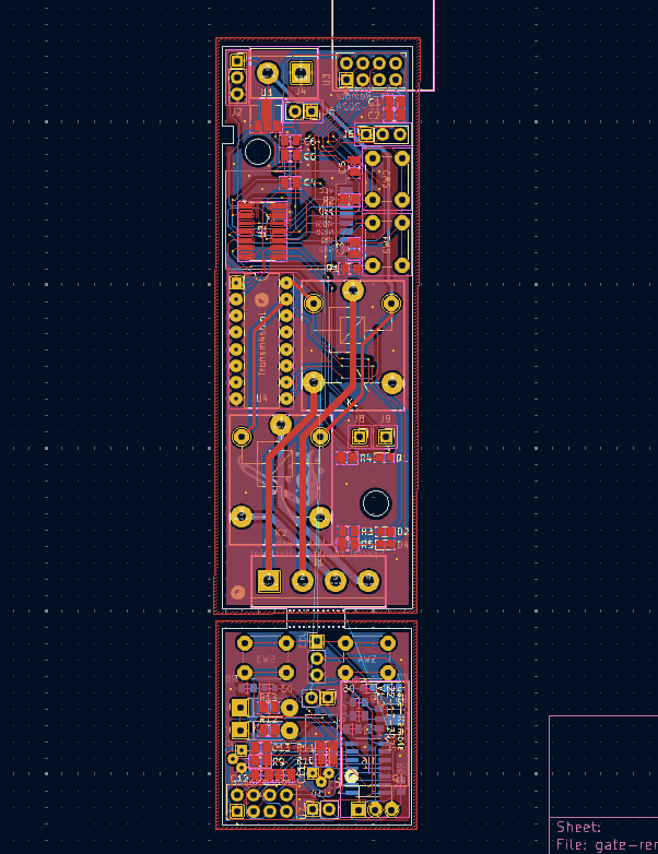
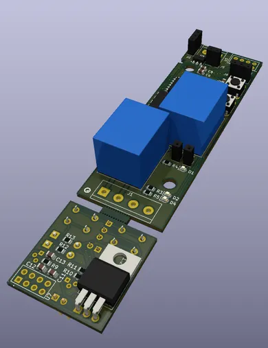
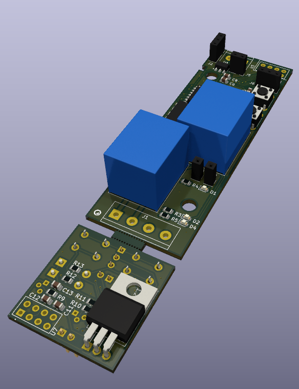
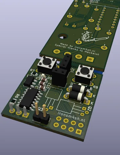
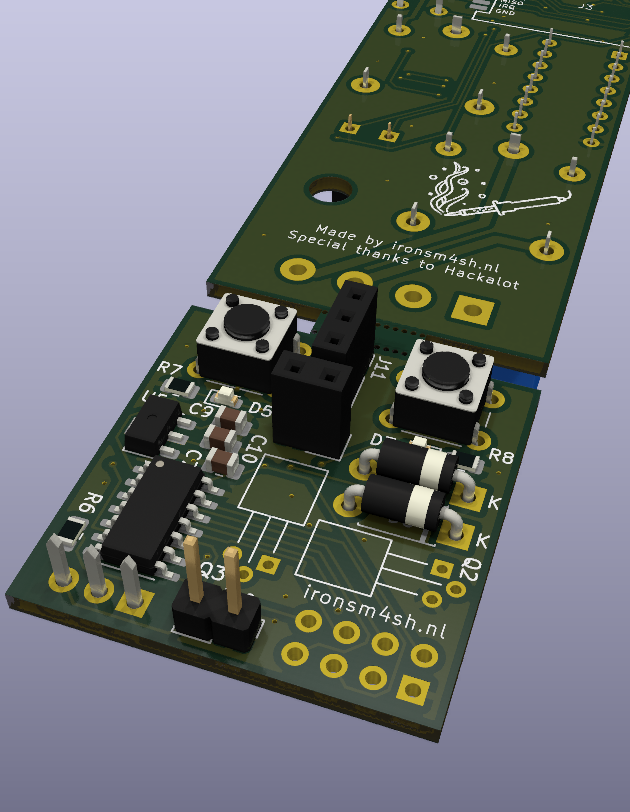
But eventually, these designs become reality, either by manufacturing them yourself or by sending them to a board-house that makes them for you. I used to create them myself, but at a certain level of detail, thats no longer a realistic option. And because Hackalot has free credits at Aisler, that is where most of my designs are made.
But at a certain point, you will also want to create a case for your circuit board. Often, a simple off-the-self case will do perfectly fine. But there are also situations where you need something special. One of such cases is a project of mine where I am working on a remote for a gate. The remote itself is small, needs a battery and a few buttons. There are no off-the-shelf solutions that tick all boxes. In the past, I often created a simple design using OpenSCAD, which is really nice (and git friendly)! But it has a couple of downsides, and one of those is that its hard to integrate your KiCad designs (If you have a good solution for this, LET ME KNOW!).
FreeCAD has been around since forever, but any of my previous attempts to use it ended with a lot of frustration. Especially the “Topological naming problem” made me think of the program as “unusable unless you know exactly what you want already”; which isn’t what CAD isn’t about in my opinion. However, there has been a recent release of FreeCAD 1.0, which supposedly made tons of improvements, and apparently solved (most of) that problem aswell.
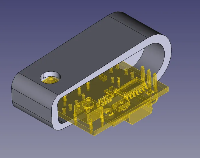
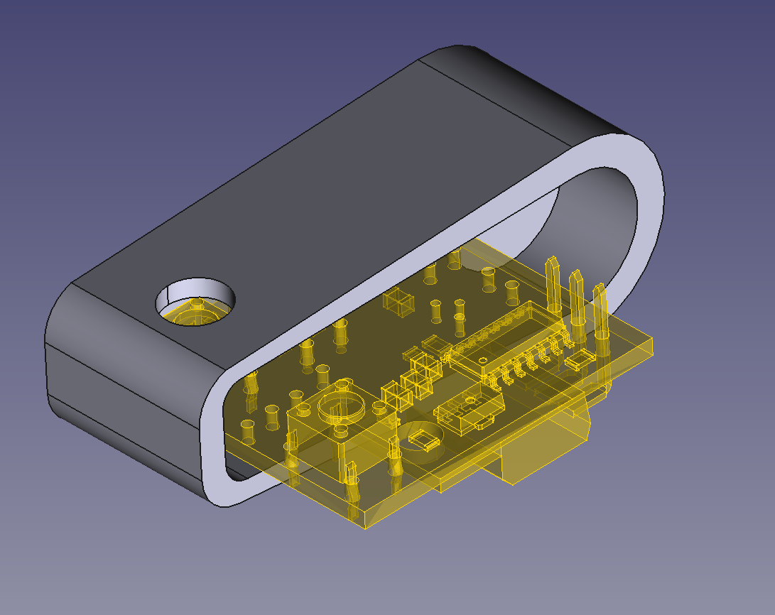
And as for the integration with KiCad, there is a plugin called the kicadStepUpMod which adds a bi-directional sync between the two programs! This means that your drawings in Kicad can be referenced in Freecad and vise versa. That is awesome, and makes designing special cases for electronics a lot easier. This is what FreeCAD looked like after importing the PCB from KiCad:
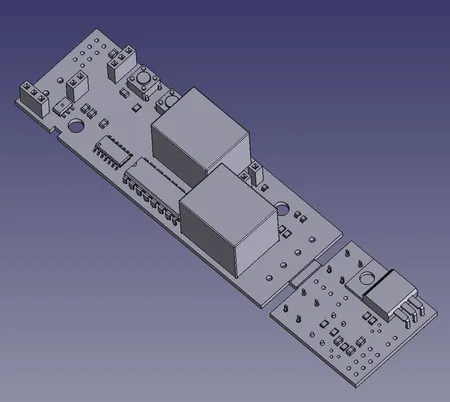
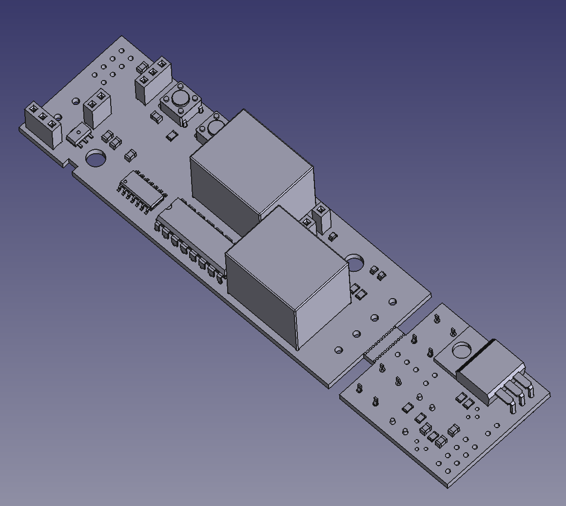
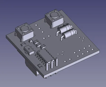
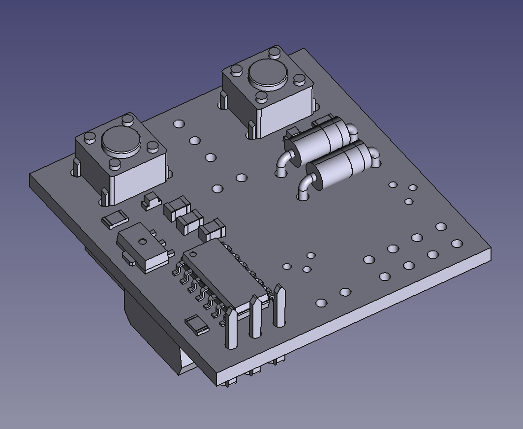
It wasn’t fully perfect, my board had break-away mouse bites, I only wanted a small part of the board. And it wasn’t centered on the document’s origin either. But both of those issues are easily fixed using some manual translation and the boolean operations of FreeCAD. After that you can simply create a body in the Part Design workbench and reference the imported PCB.
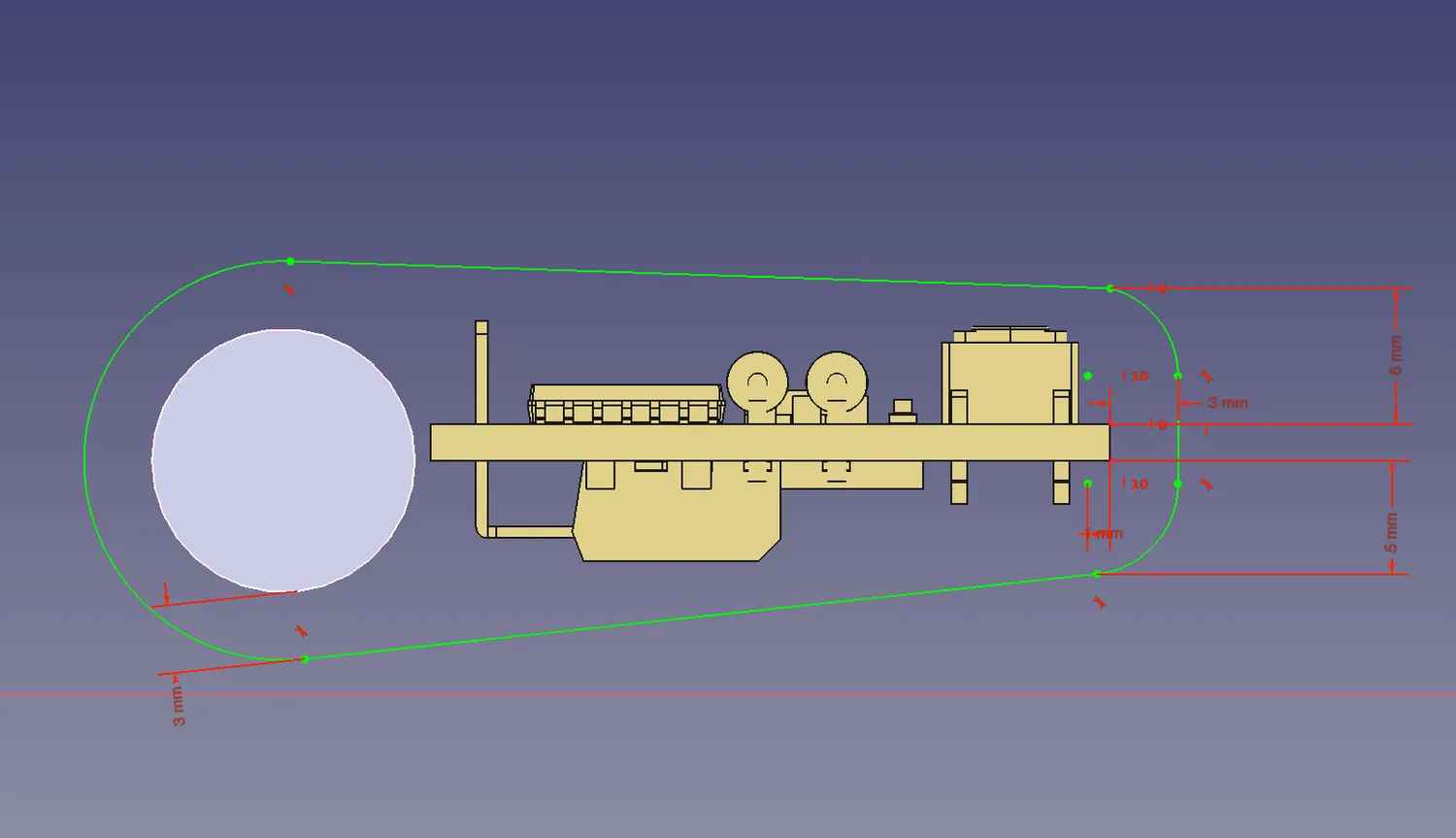
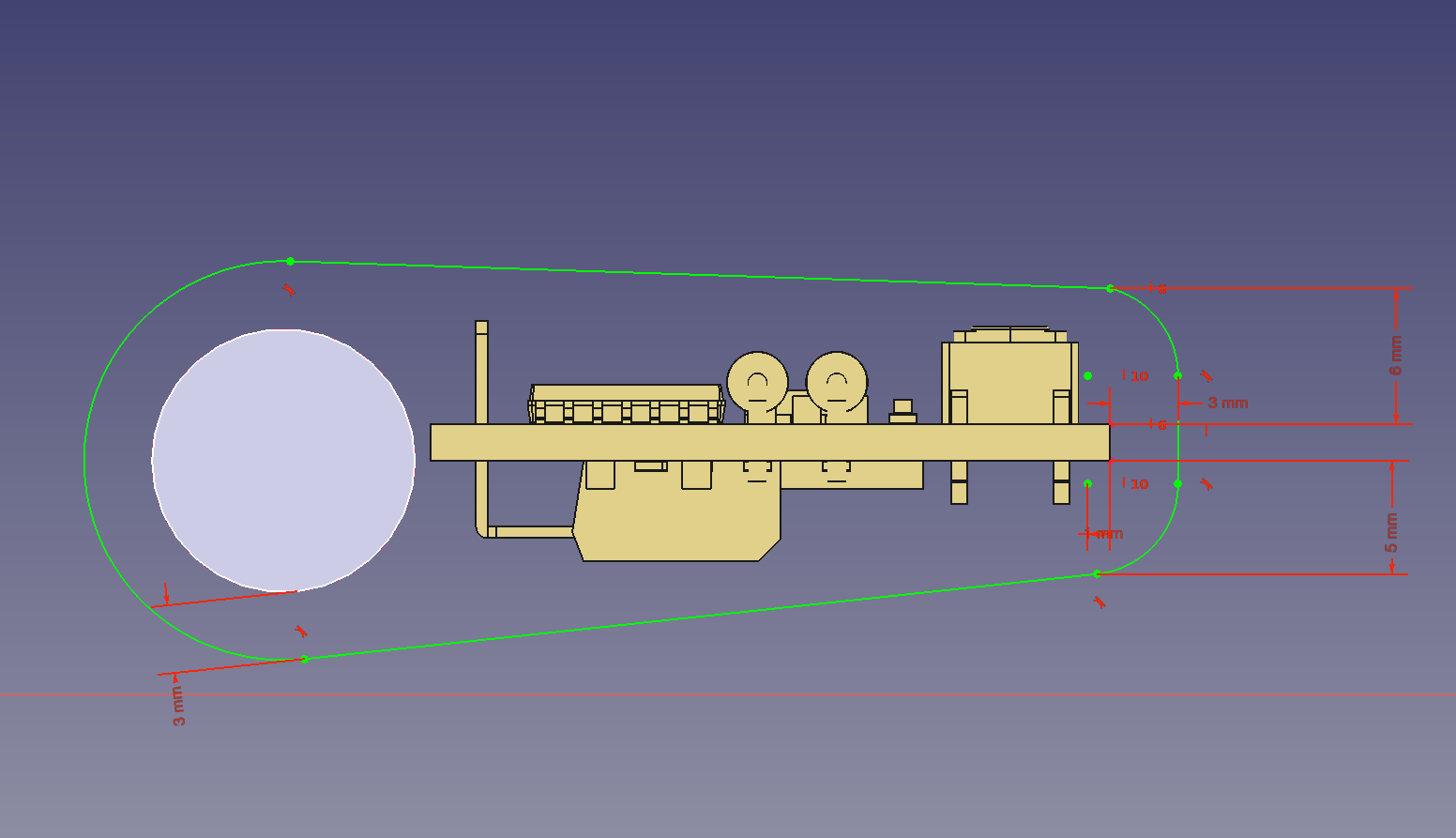
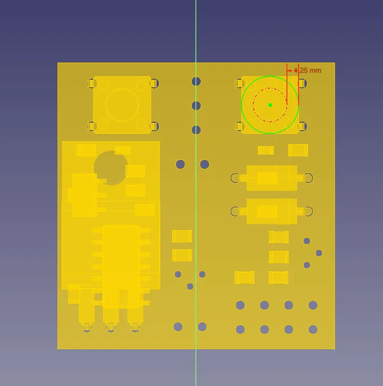
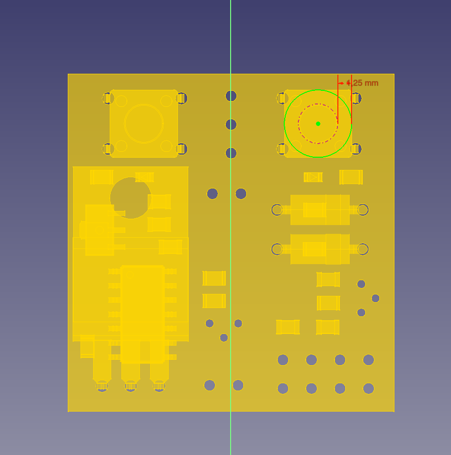
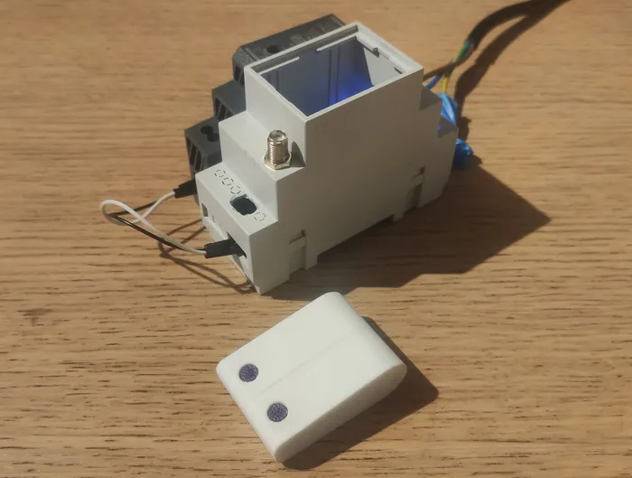
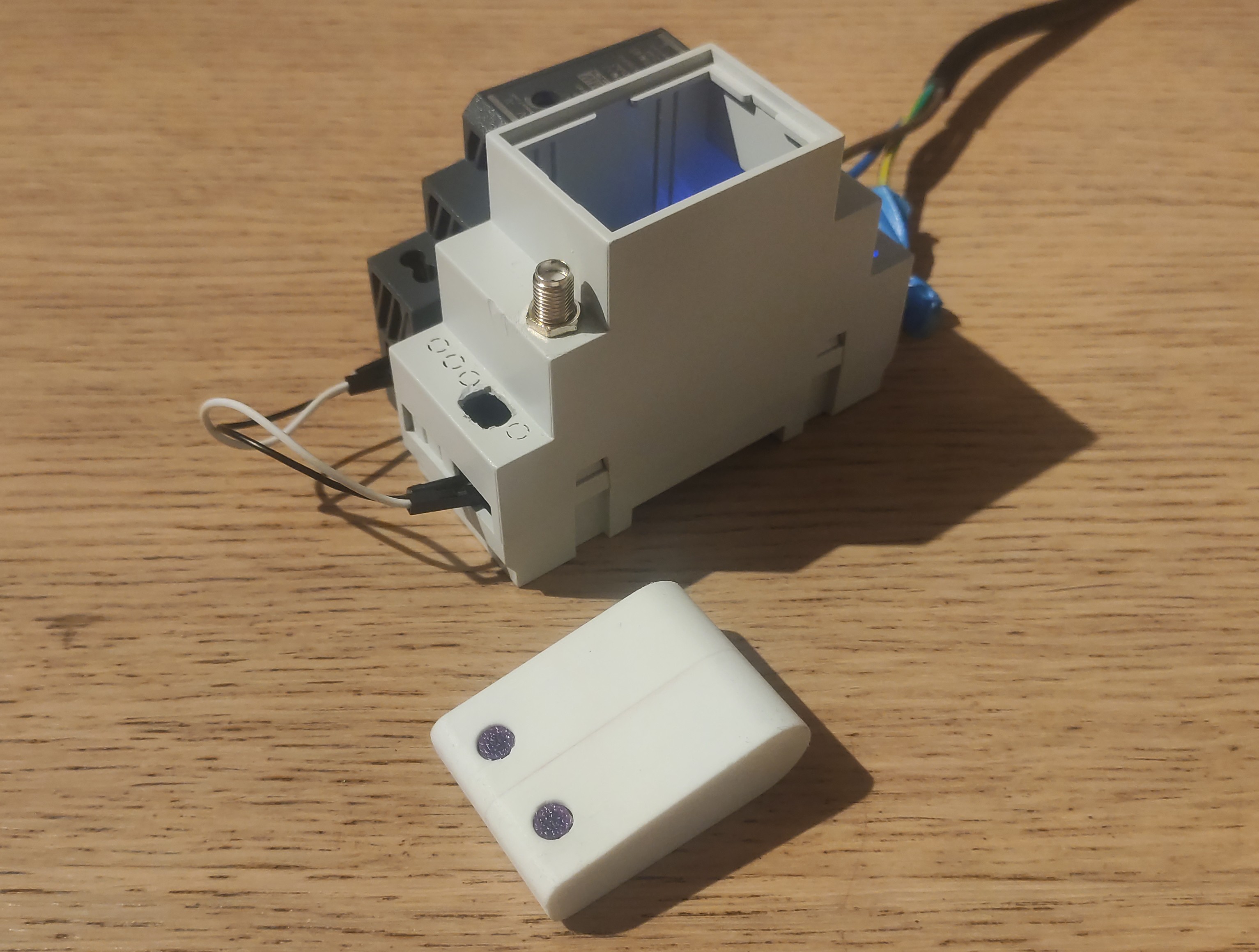
As you can see in the images above, I can create constrains based on the circuit board, and everything works as you’d expect. My overall experience with FreeCAD 1.0 has been very pleasant! I encountered a few bugs/crashes, but nothing too big, and no showstoppers. In the end I can happily recommend this workflow to anyone that has similar needs/constraints in their projects. The 3D printed remote can be seen in the picture below, together with the final FreeCAD design (half of it):
