Making a parking sensor
I recently bought a new car, a Ford Ka from 2008. This car is much newer than my previous Citroen AX from 1993. The difference between 15 years of automotive innovation is clearly noticable, the Ka has fancy features such as electric windows, AC, and central door locks. However, it still lacks really fancy features such as a parking sensor. That is why I set out to create a parking sensor using easily available components, which I could install in my Ford Ka.
What is a parking sensor?
A parking sensor is in essence just a tool to prevent the driver from driving into objects while driving backwards. Some modern variants have a camera with a giant FOV and a big display on the car’s dashboard, while others have a more modest distance sensor that simply beeps at the user if the car’s rear is close to something. Creating a camera based solution sounds complicated, especially since the Ford Ka does not have a place on the dashboard where a display would fit. That is why I opted to create a solution based on cheap and simple ultrasonic distance sensors. The sensor I picked is the AJ-SR04M, which can be bought from the TinyTronics.
Ofcourse, just the sensors alone are not enough, their data also needs to be consumed, processed and made available (visually and audibly). That is why I also bought the ESP32 based TTGO T-Display and a few buzzers. The ESP32 can process the measured distance, draw it on the screen and, if needed, warn the driver if an object is too close using a buzzer.
Connecting multiple distance sensors
The AJ-SR04M is by default the same as most basic Arduino distance sensors, where it sends a periodic pulse that indicates the distance it measures. This is less than ideal because it requires a lot of wires if multiple sensors are combined, and the speed at which the distance can be obtained is really low. However, the distance sensor has multiple modes that can be set by soldering a resistor to the PCB.
| Mode | Description | Resistor |
|---|---|---|
| 1 | Pulse mode | N/A |
| 2 | Serial mode (automatic) | 47K |
| 3 | Serial mode (manual) | 120K |
I connected a 47K resistor, and set the sensor to mode 2. In this mode, the sensor measures periodically, and then transmits the value using a serial connection. The data it transmits looks as follows:
0xFF, H_DATA, L_DATA, SUM
H_DATA: upper 8 bits
L_DATA: lower 8 bits
SUM: 0xFF + H_DATA + L_DATA
This makes the signal easy to process, as most microcontrollers have an internal USART mode which can receive the data. Sadly, the ESP32 doesn’t have four USART receivers, so it can’t consume all sensors directly. In the previous blogpost, I made a small ATtiny404 bases USART -> I2C module. This module was made for the parking sensor, and it allows us to connect multiple distance sensors to a simple I2C bus, which the ESP32 can easily consume.
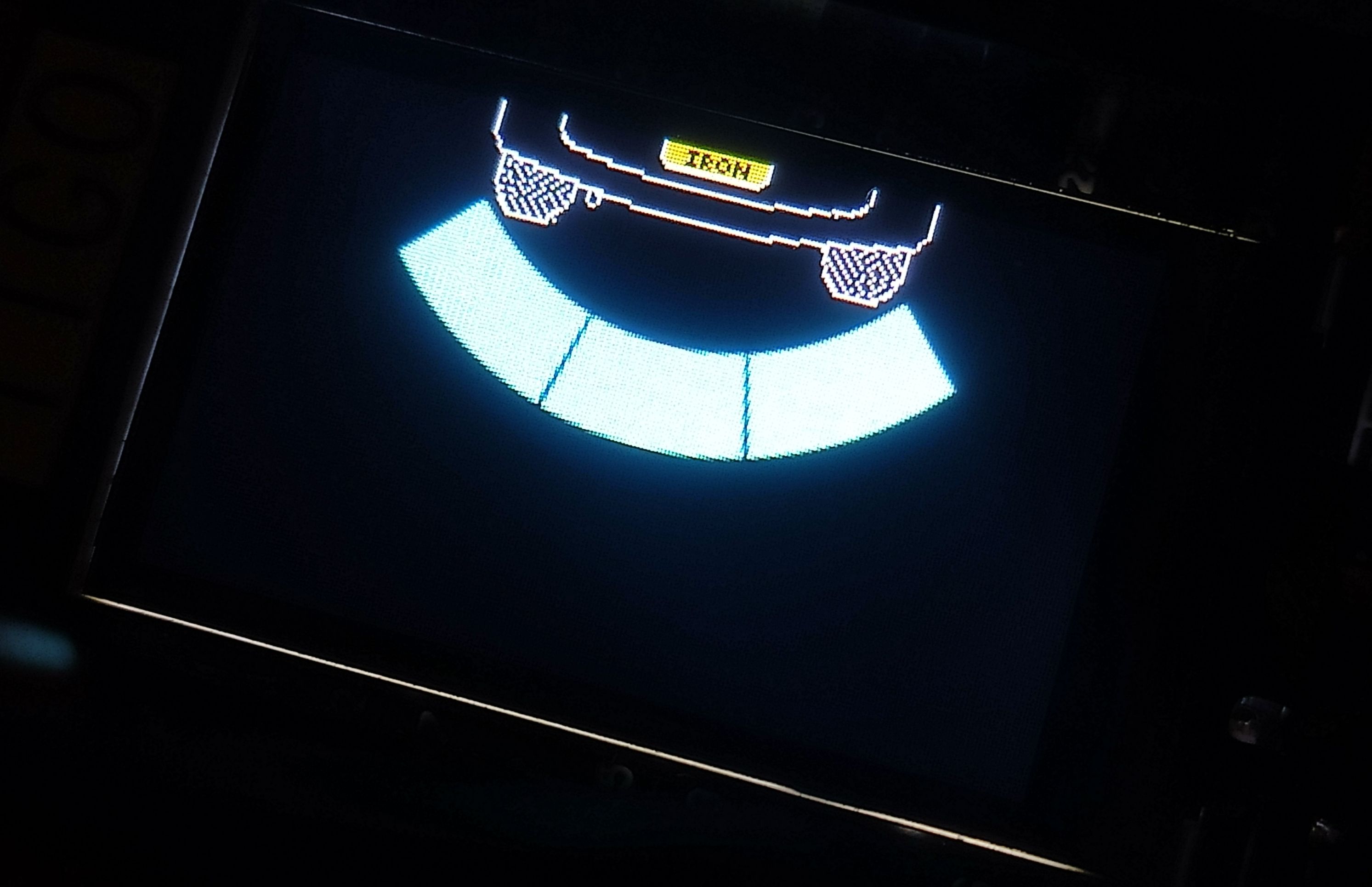
Displaying the information
The ESP32 has a small display, which can easily be controlled using the TFT_eSPI library. Drawing images is as simple as the following code:
TFT_eSPI tft = TFT_eSPI();
const unsigned char IMG_BACKGROUND[] = {...}
tft.drawXBitmap(60, 0, IMG_BACKGROUND, 120, 28, (uint16_t)0xffffff);
Where IMG_BACKGROUND is a byte array that was generated using img2cpp. Combine the ability to draw images with the ability to draw arcs, and you are left with a very simple and clean diplay for a parking sensor.
const uint16_t START_ANGLE[3] = {16, 345, 314};
const uint16_t END_ANGLE[3] = {46, 15, 344};
sprite.createSprite(tft.width(), tft.height());
sprite.fillSprite(TFT_TRANSPARENT);
for (uint8_t i = 0; i <= 2; i++)
{
  uint16_t distance = 0;
  readSensor(&distance, i+1);

  sprite.drawSmoothArc(120, -30, 210, 80, START_ANGLE[i], END_ANGLE[i], 0, 0, false);
  uint16_t width = map(distance, 0, 2200, 80, 160);
  sprite.drawSmoothArc(120, -30, width, 80, START_ANGLE[i], END_ANGLE[i], TFT_CYAN, 0, false);
}
sprite.pushSprite(0, 0, TFT_TRANSPARENT);
sprite.deleteSprite();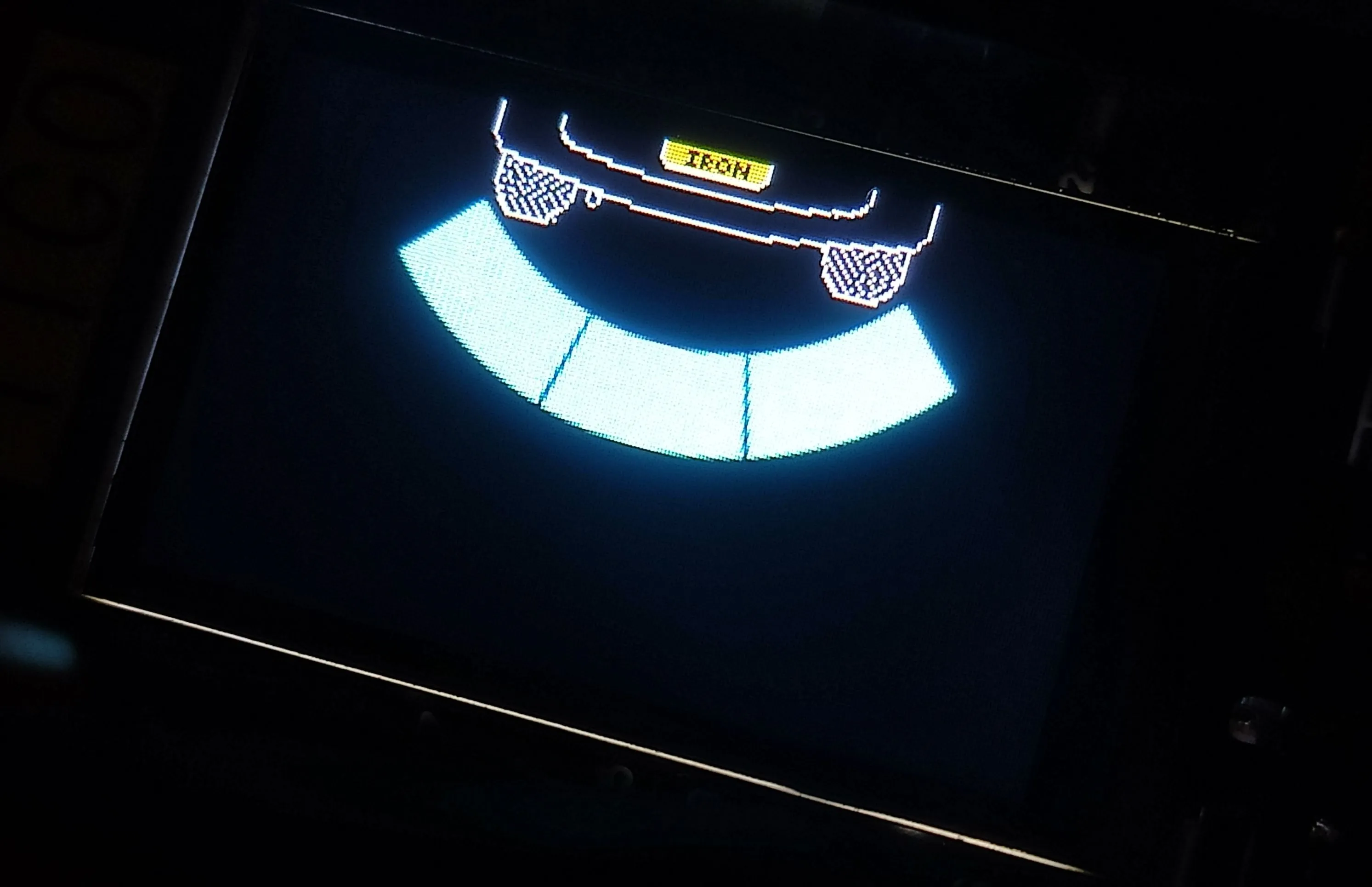
Next steps
The project is slowly progressing, and its currently a fun prototype. However, the project is still far from complete. In future blogposts I will add the following:
- Connect an RTC, and add the ability to display a clock when the driver is not driving in revserse gear.
- Design a PCB for the entire project because a breadboard won’t survive more than a few meters in a car.
- Installing the project into my car.
If you spot any mistakes or if you would like to contact me, visit the contact page for more details.