Analyzing the power usage of small devices
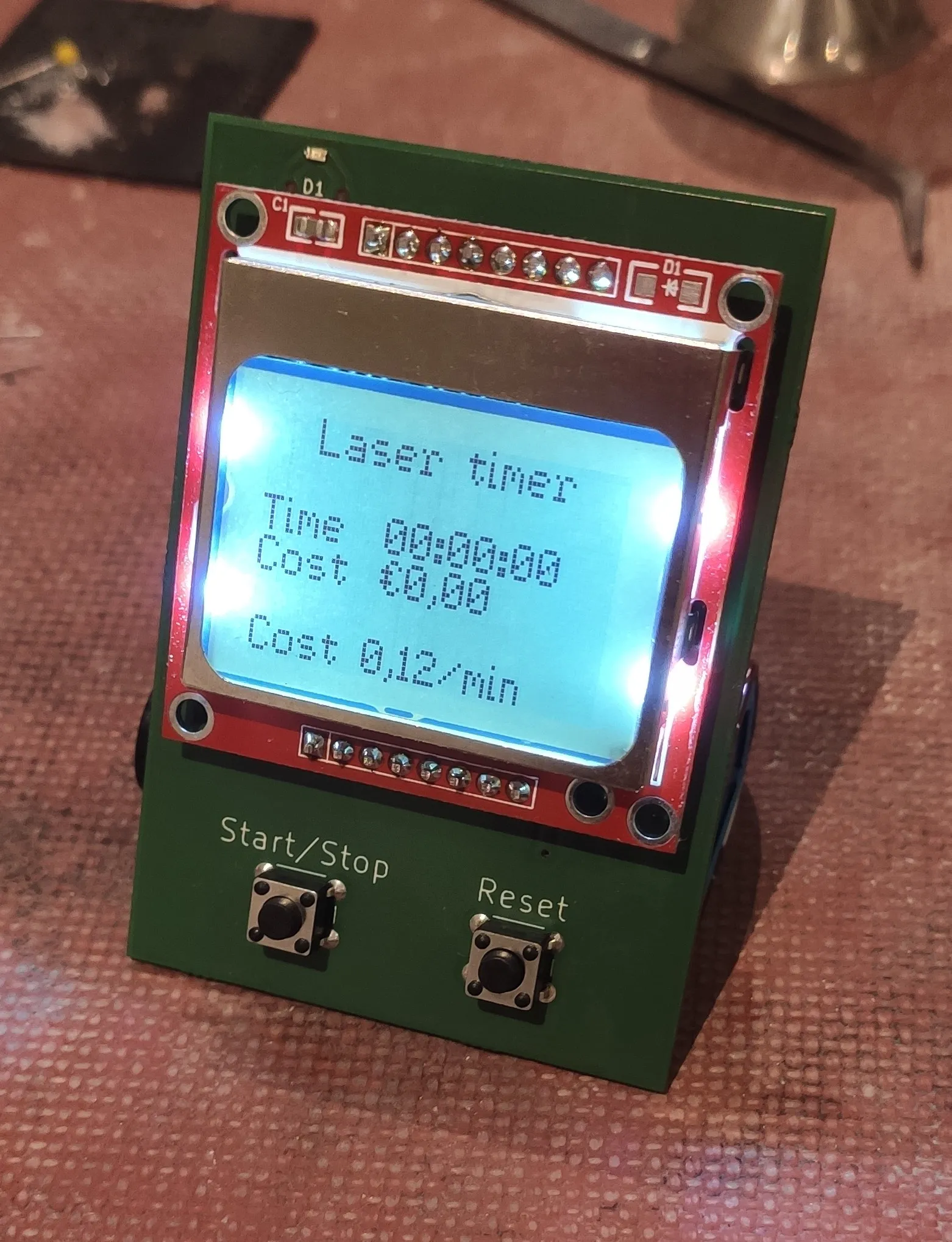
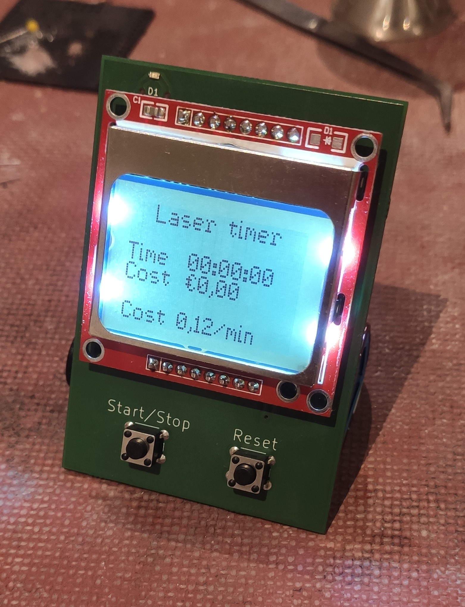
I recently created a small timer to calculate the costs of using the laser cutter at my local hackerspace. This timer is fairly simple and uses an ATmega8U2, and a LCD display from an old nokia device (PCD8544). However, even though I implemented proper usage of sleep modes, the battery was still empty after a few weeks. This was way sooner than expected, the battery should last at least a year. An example of the code used in the timer can be seen below.
clock.SetMode(Nori::TimerMode::CTC)
    ->SetClockSource(Nori::ClockSource::ClkDiv256) // 8000000 / 256 = 31250 Hz
    ->SetLimit((uint16_t)31250)                    // 31250 / 31250 = 1 Hz
    ->AttachInterrupt([]() {
      if (running) {
        set_sleep_mode(SLEEP_MODE_IDLE);
        duration++;
        return;
      }

      idle++;
      if (idle > THRESHOLD) {
        set_sleep_mode(SLEEP_MODE_PWR_DOWN);
      }
    });

// Other interrupts (eg. to wake or enable the device) are hidden.

set_sleep_mode(SLEEP_MODE_PWR_DOWN);
while (true) {
  sleep_mode();
}
This means that the timer should nearly always be in its PWR_DOWN mode; where it barely uses any power. Yet the battery ran out in a matter of weeks with barely any usage. Strange. To find out the usage of the device, one could use a multimeter, but it is really hard to visualise the extremely irregular usage patterns of a microcontroller using a multimeter.
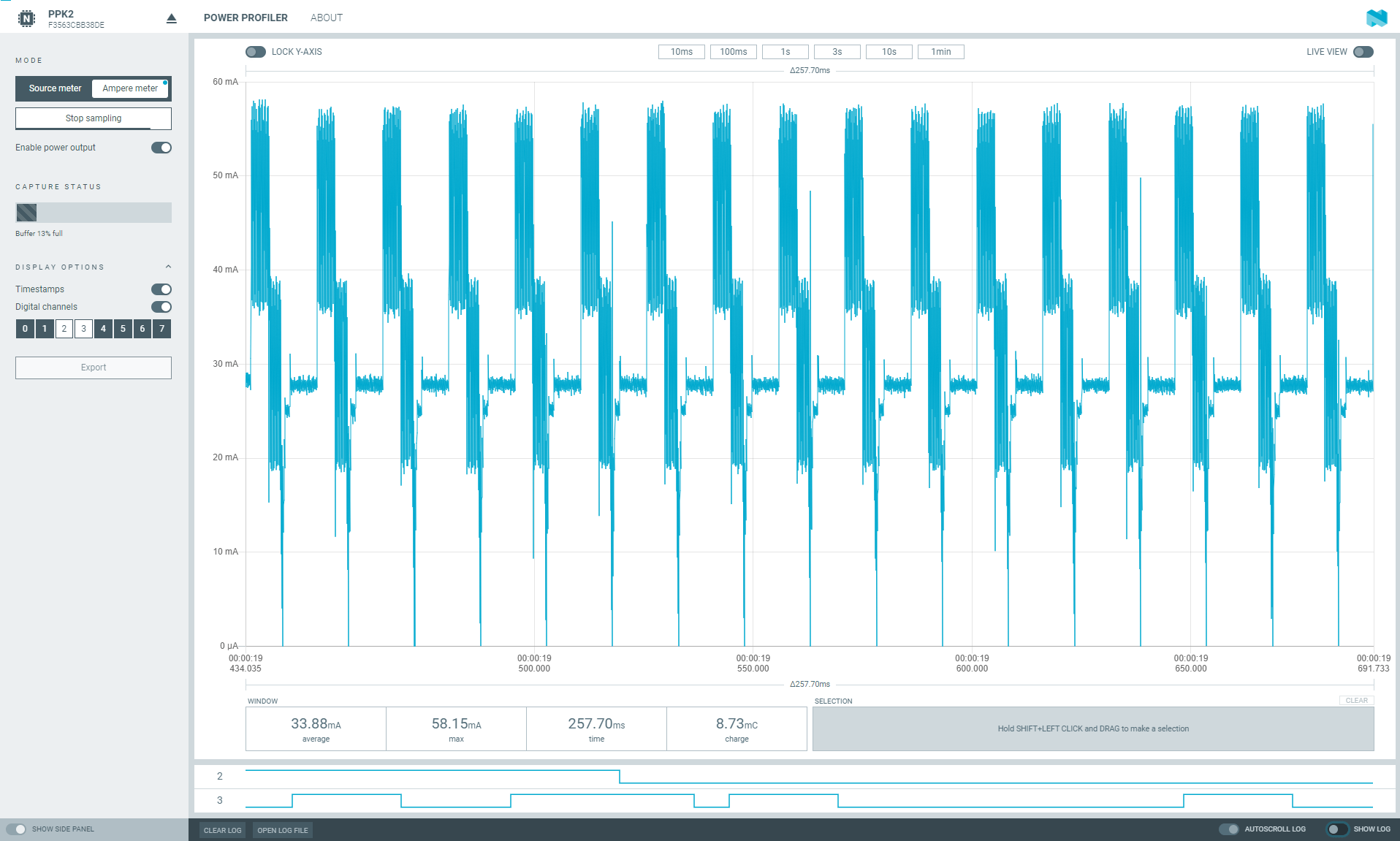
To solve the issue of very irregular power consumption, tools like the Power Profiler Kit II exist. These devices are like an oscilloscope for current combined with a logic analyzer. However, at a price of around €100 the PPK2 costs too much for my very limited use.
Power measurement
Noric’s power profiler kit works by measuring current 1000’s of times a second, and then plotting it in software called nRF Connect. A screenshot of nRF Connect can be seen below (source: cnx-software.com).

I want to be able to do that; but then without the PPK2. Because here are no cheap solutions online, I decided to create my own variant. thus the Nori Power Analyzer was born. This is a very simple device which can do all the things the PPK2 can do, just a lot slower. The PPK2 can measure at 100ksps — 100 kilo samples per second, that is 100 kHz. My version is powered using a ATmega8U2, so 100ksps is out of reach (for now). I managed to reach 1ksps. Which is, while only 1% of the PPK2, still sufficient for my usecase.
Nori Power analyzer
As any electronics project, it starts with an idea, a breadboard and a bunch of components. I picked up an I²C capable current sensor and got to work. After carefully reading through the INA219’s datasheet and a very helpful article, I could use the INA219 without any issues.
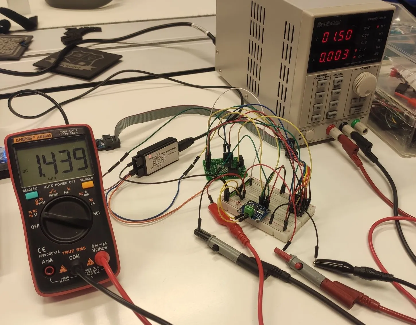
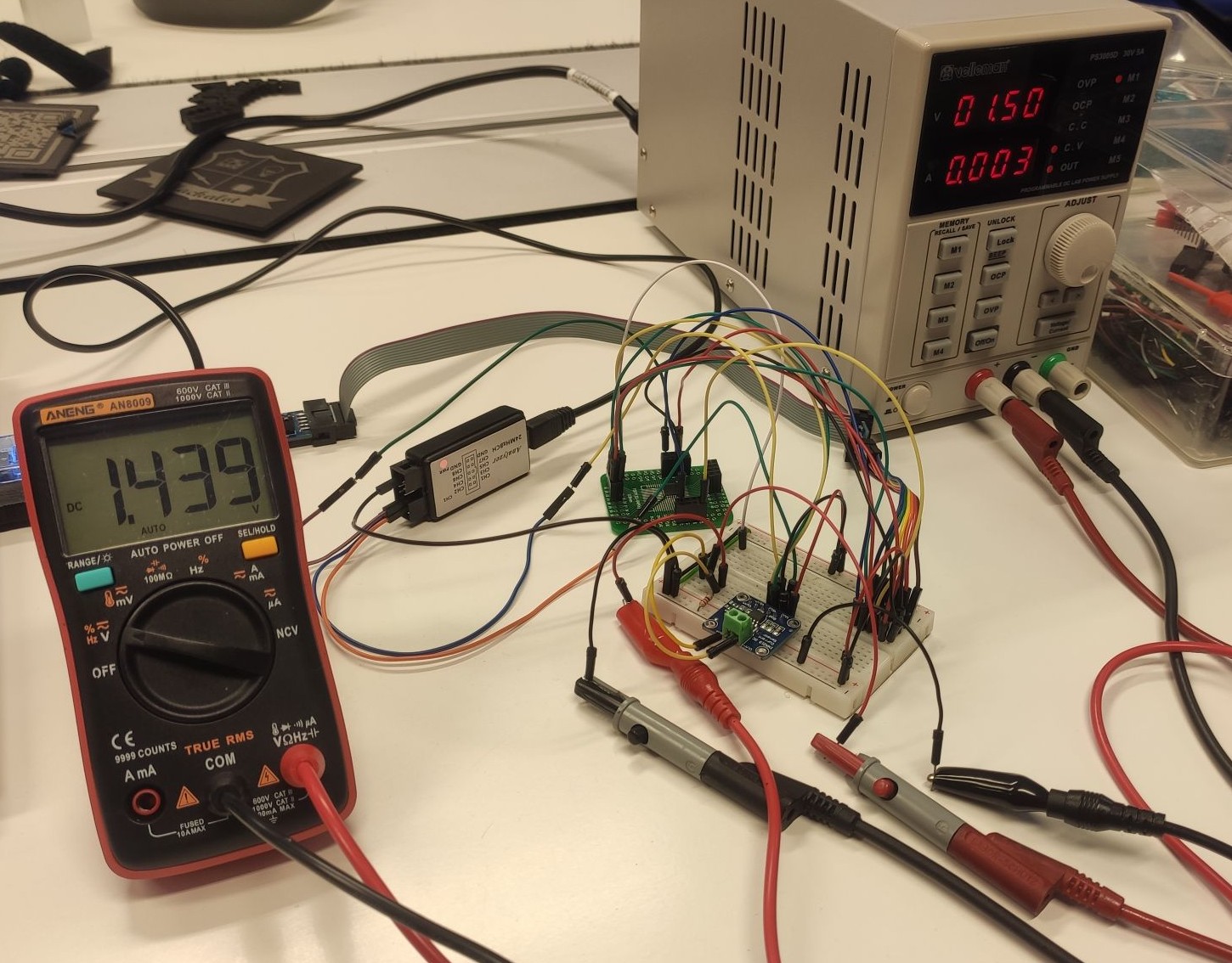

Where the INA219 is attached to a 1.439V bus according to my multimeter, while the INA219 agrees and reports a voltage of 0x059C (1436mV). That is spot on! Within 3mV!
After some USB Adventures my ATmega8U2 could also communicate with a computer.
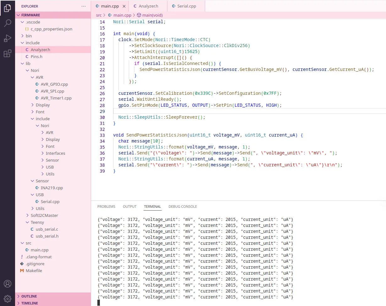
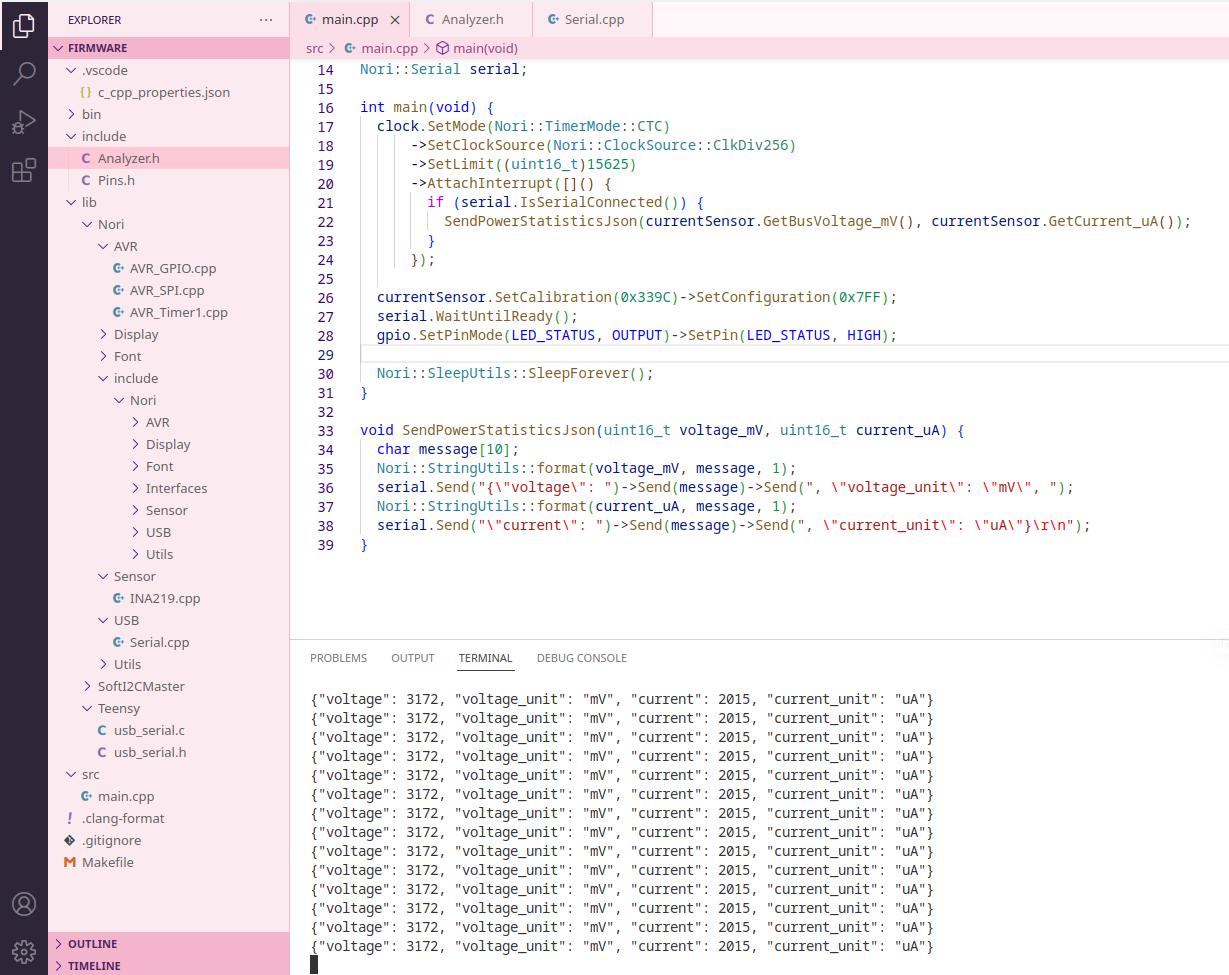
While the first version was very slow (~2Hz), it was a very promising beginning. Now there were two tasks left:
- Visualising the data on a computer
- Increasing the speed as much as possible
Visualising the data
To visualise the data, I decided to learn something new, EGui. EGui is a immediate GUI framework for Rust. At first my experience using the builtin plot functionality was very promising. A plot with mock data is shown below:
But adjusting the builtin plot to my desired result proved to be challenging, and would require more work than I was willing to invest. Especially when all the other functionality needed to be implemented aswell. So I decided to jump ship to a proven and much more mature technology — Sigrok. Sigrok is a library that can be used to interface with all kinds of electronics like Multimeters, oscilloscopes, power supplies and logic analyzers. After a few hours of hacking, I managed to add a custom device to Sigrok and use it in PulseView; even if it is just primitive mock data for now.
// Mock data for Sigrok
float value = (float)++devc->state;

if (devc->state >= 20) {
  devc->state = 0;
}
implementating a Sigrok device
implementing a Sigrok device is fairly simple, you just need to implement the following struct:
static struct sr_dev_driver nori_power_analyzer_driver_info = {
  .name = "nori-power-analyzer",
  .longname = "Nori power analyzer",
  .api_version = 1,
  .init = std_init,
  .cleanup = std_cleanup,
  .scan = scan,
  .dev_list = std_dev_list,
  .dev_clear = std_dev_clear,
  .config_get = config_get,
  .config_set = config_set,
  .config_list = config_list,
  .dev_open = dev_open,
  .dev_close = dev_close,
  .dev_acquisition_start = dev_acquisition_start,
  .dev_acquisition_stop = dev_acquisition_stop,
  .context = NULL,
};
Sigrok will call the functions and process the outgoing data. It also provides default implementations for certain parts. You just need to implement the following:
- Detecting your device from the computer
- Specifying the capabilities of your device
- Starting/Stopping a session on your device
- Getting measurements from your device
- Setting configurations such as samples/second or total sample count.
Most of these methods are trivial; and can be copied from the Demo or tondaj-sl-814 device. The following method is used to start a session:
static int dev_acquisition_start(const struct sr_dev_inst *sdi) {
  struct dev_context *devc = sdi->priv;
  struct sr_serial_dev_inst *serial;

  std_session_send_df_header(sdi);

  sr_sw_limits_acquisition_start(&devc->limits);

  serial = sdi->conn;
  serial_open(serial, SERIAL_RDWR);
  serial_source_add(sdi->session, serial, G_IO_IN, 500,
                    nori_power_analyzer_receive_data, (void *)sdi);

  return SR_OK;
}
After that, Sigrok will continiously keep calling nori_power_analyzer_receive_data until all samples are collected. That is implement as follows:
SR_PRIV int nori_power_analyzer_receive_data(int fd, int revents,
                                             void *cb_data) {
  struct sr_dev_inst *sdi;
  struct dev_context *devc;
  struct sr_serial_dev_inst *serial;

  (void)fd;
  (void)revents;

  sdi = cb_data;
  serial = sdi->conn;
  devc = sdi->priv;

  for (uint8_t channel = 0; channel < NUM_OF_CHANNELS; channel++) {
    uint8_t index = 0;
    serial_read_blocking(serial, &index, 1, 100);
    uint16_t data = 0;
    serial_read_blocking(serial, &data, 2, 100);

    switch (index) {
    case 1: { // Logic
      send_digital_packet(sdi, data);
      break;
    }

    case 2:   // Voltage
    case 3: { // Current
      send_analog_packet(sdi, (float)data, index);
      break;
    }

    default: {
      sr_err("Unsupported channel index: %d ", index);
      break;
    }
    }
  }
  sr_sw_limits_update_samples_read(&devc->limits, 1);

  if (sr_sw_limits_check(&devc->limits)) {
    sr_dev_acquisition_stop(sdi);
  }
  return TRUE;
}

static void send_digital_packet(struct sr_dev_inst *sdi, uint8_t value) {
  struct sr_datafeed_packet packet;
  struct sr_datafeed_logic logic;

  packet.type = SR_DF_LOGIC;
  packet.payload = &logic;
  logic.unitsize = 1;
  logic.length = 1;
  logic.data = &value;

  sr_session_send(sdi, &packet);
}

// send_analog_packet is left out for brevity.
And that is all there is to it! After this, Sigrok supports your device and programs such as Sigrok-CLI, PulseView or SmuView can use your device. PulseView can be seen below:
Increasing the speed as much as possible
To make the power analyzer usable, it needs to be able to create many measurements per second. The speed is purely bottle necked by the ATmega8U2, Sigrok can easily process 24000000 data points per second. The ATmega8U2 only processes 8000000 instructions per second, so saturating Sigrok won’t happen anytime soon. The Atmega8U2 spends 99% of the time on just two things:
- Read the INA219
- Transmit data via USB
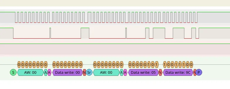
So increasing the throughput is done by optimizing those methods. Optimizing the USB is simple; just transmit less data! The rest is fixed-function hardware and can not be made faster. So I created a simple and minimal protocol which requires just 12 bytes for a full measurement:
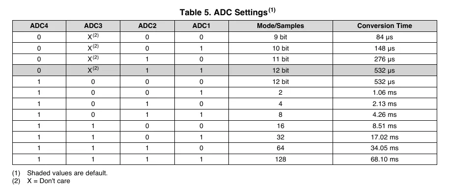
Unfortunately, increasing the speed of reading the INA219 is harder. The ATmega8U2 does not support hardware I²C, so all communication needs to be bit-banged using software (or a different chip needs to be used to convert the INA219’s data to SPI). I am using SoftI2CMaster to communicate with the INA219. The library supports a I2C_FASTMODE which can transmit bits at ~300 kHz. The INA219 itself supports much higher clocks up to 2.56 MHZ. But the INA219 can only measure once per 0.532ms at an accuracy of 12 bits. This means that the highest clean frequency without any repeating measurements is 1kHz.

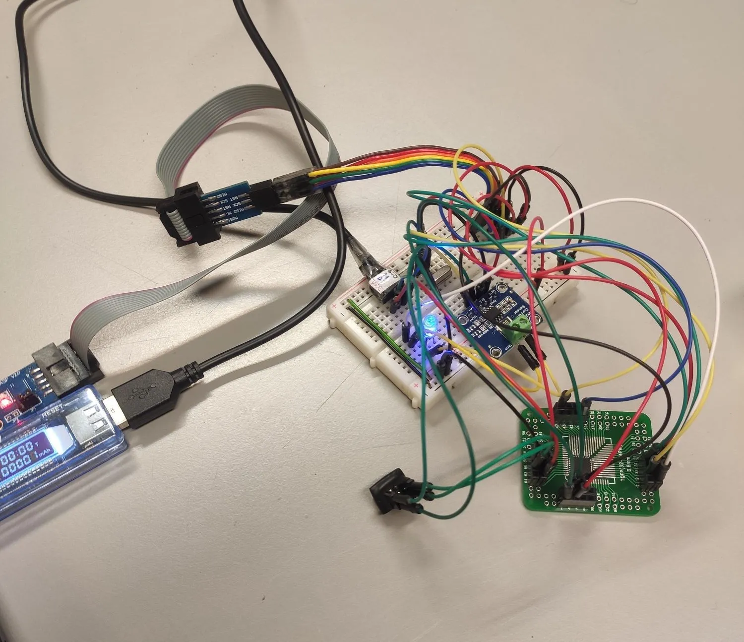
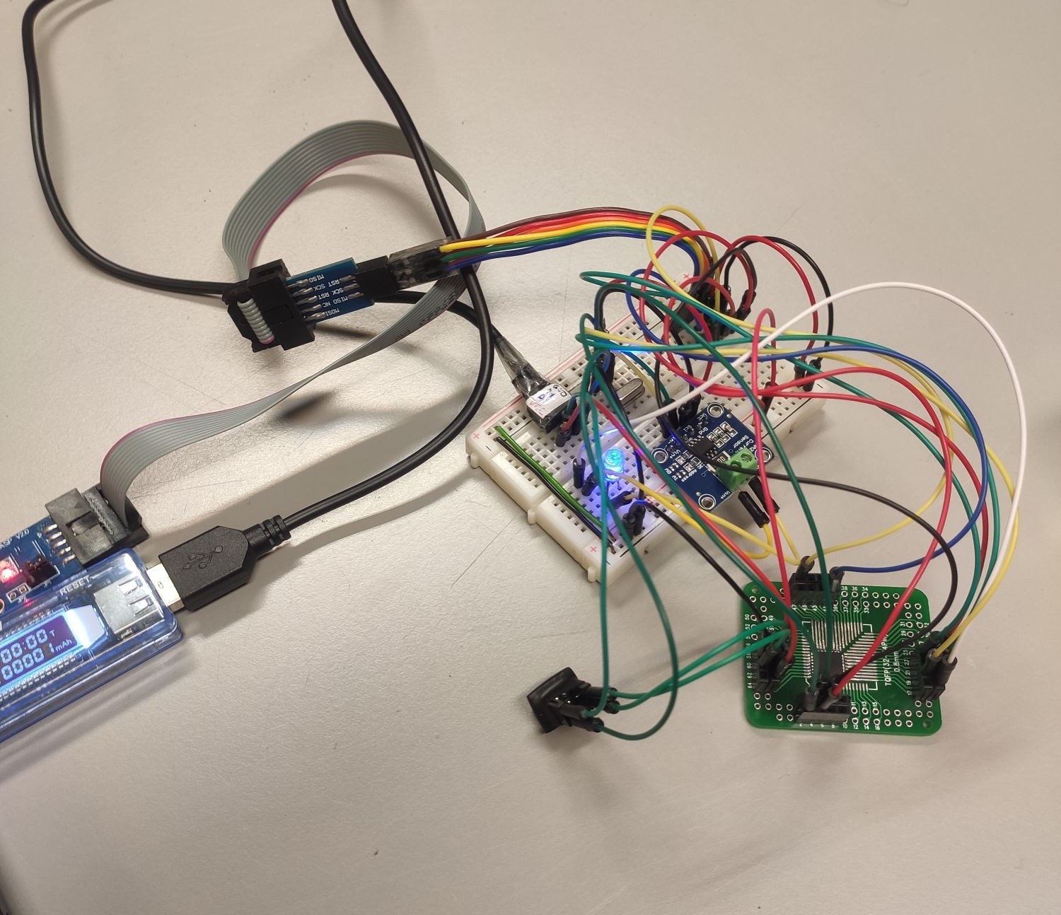
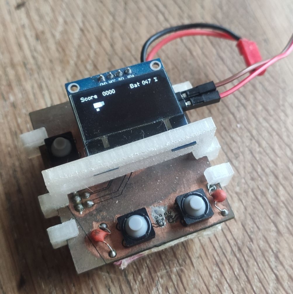
A working prototype
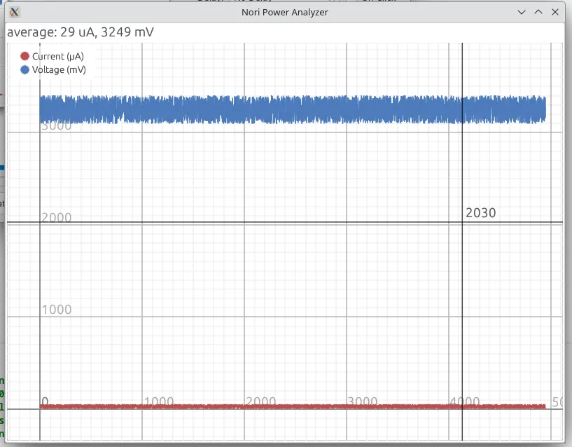
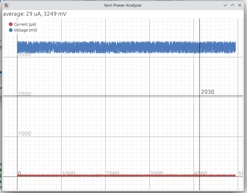
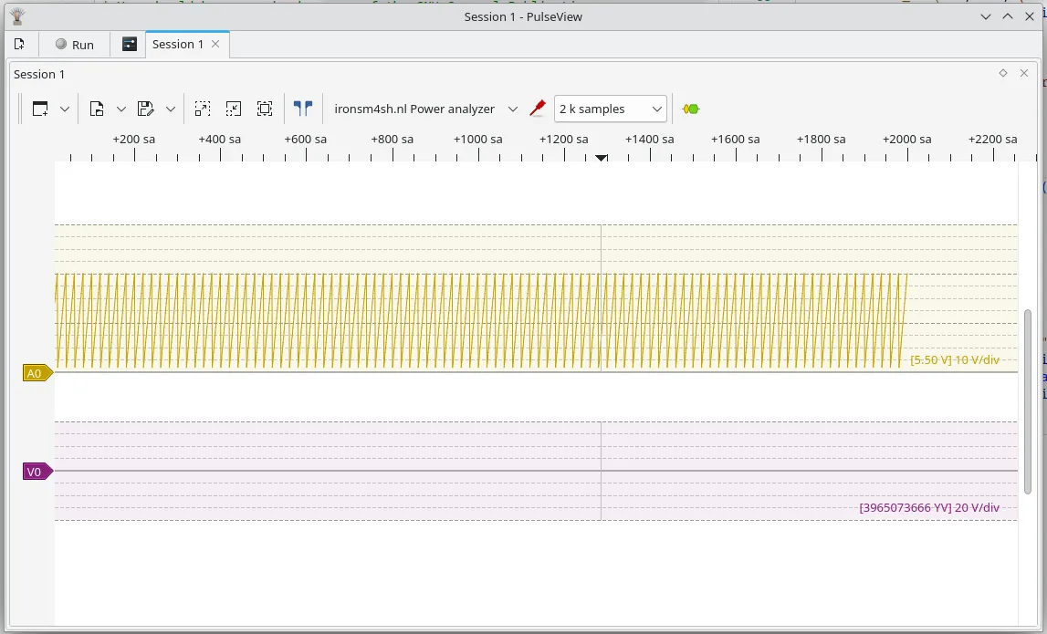
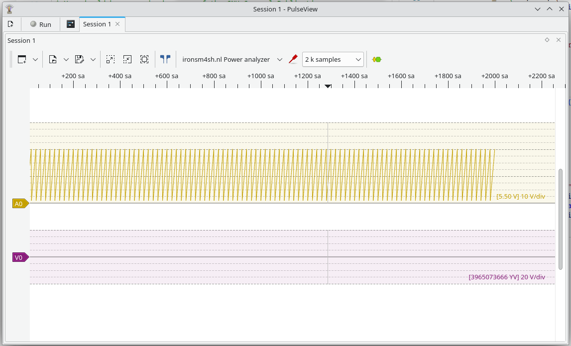
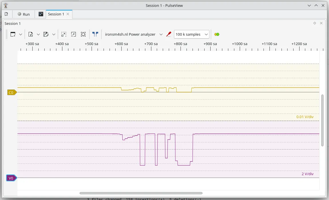
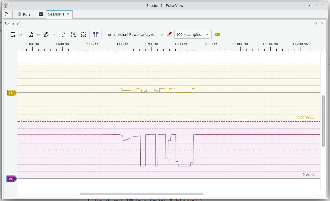
Combining all parts above, results in a fully functioning prototype that can measure 1000 times per second and is viewable in PulseView. A while ago I made a small game, and I never knew how much power it actually used. Time to test!

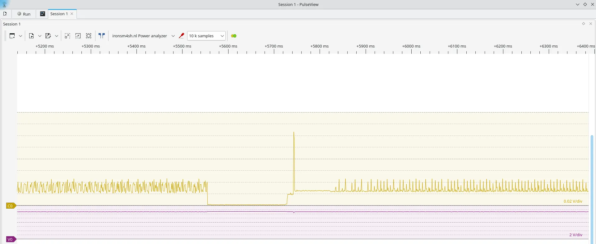
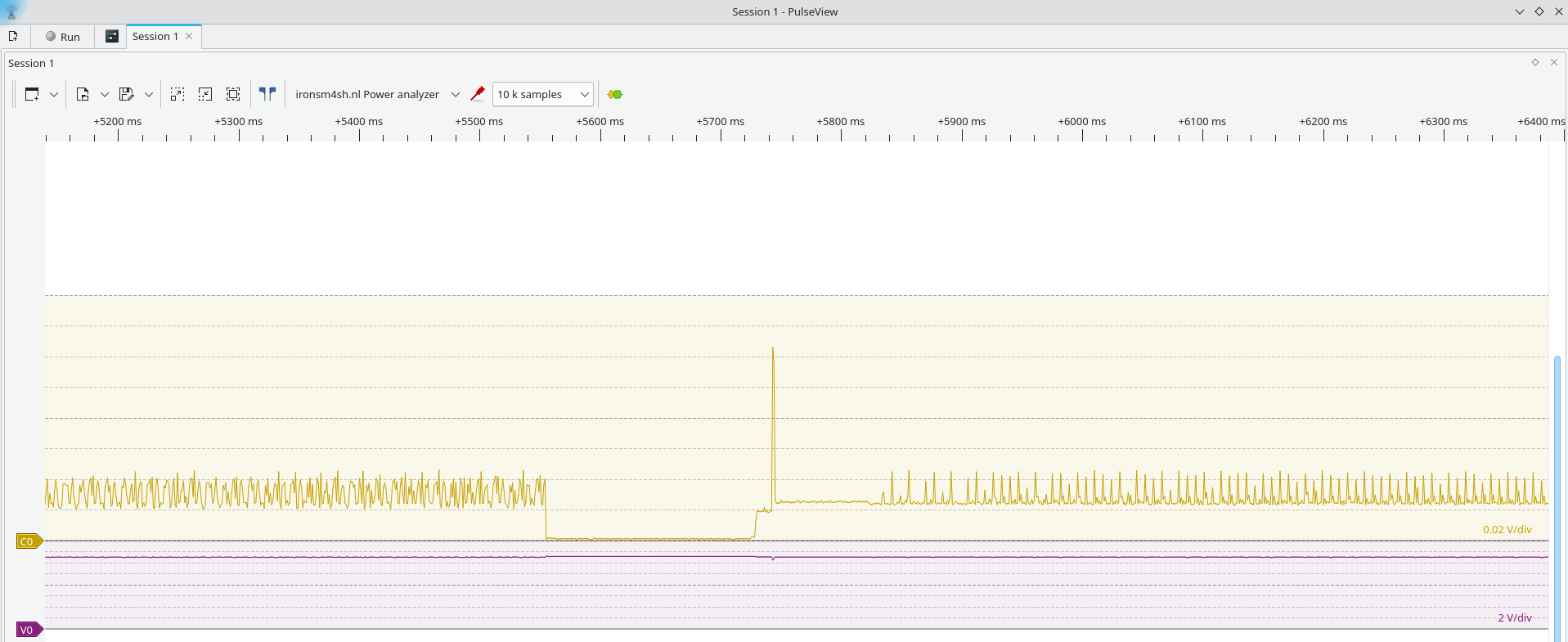
Success! I can clearly see how much power the snake game is using when its starting, playing, game over or standby.
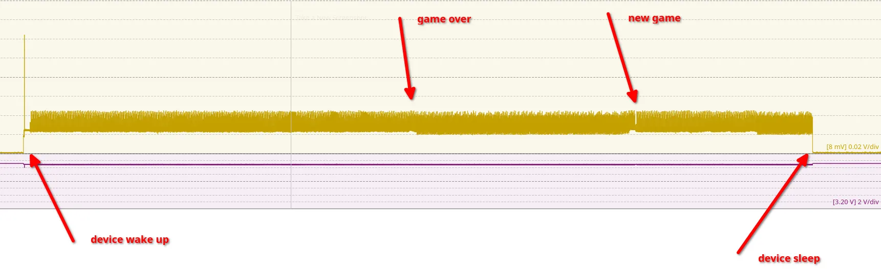
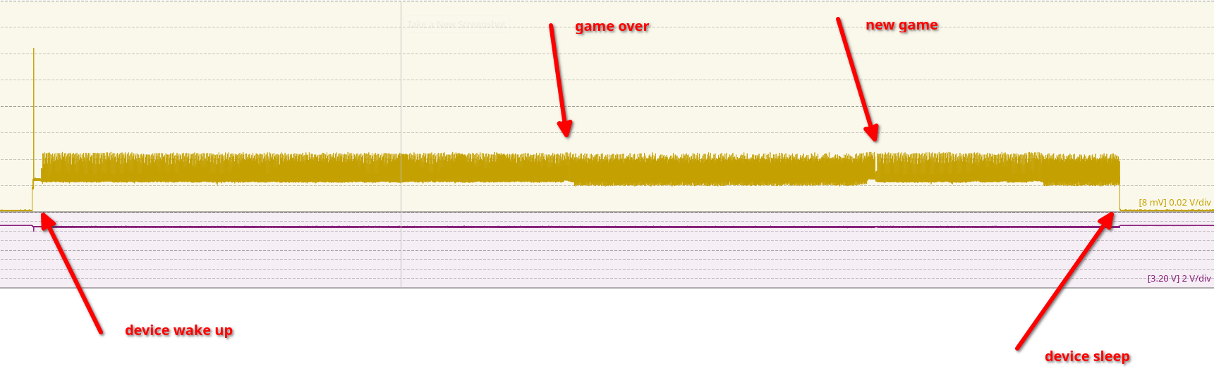
Note: There is a bug in PulseView where any channel shows a voltage; even when amperes are being supplied.
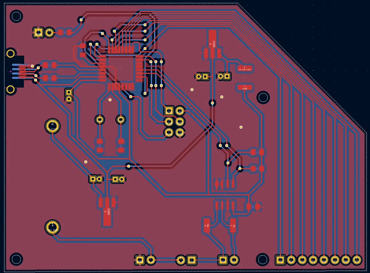
In the next post, I will combine all elements into a finished product that can be used to measure the current of all kinds of small devices without the fragile breadboard connections. A preview can be seen below:

If you spot any mistakes or if you would like to contact me, visit the contact page for more details.